

Quick Answer
U0155 means Lost Communication with Instrument Panel Cluster (IPC) Control Module. A reporting module stopped receiving expected cluster messages. It does not prove the cluster is defective. First save the full vehicle scan, identify who recorded the fault and check whether the cluster can communicate now. Then test the required power, ground and network paths using the vehicle-specific diagram.
What Does the U0155 Code Mean?
The U0155 code is a communication fault. The instrument panel cluster displays gauges and warning information, but those readings depend on messages exchanged with other modules. A receiving module can record U0155 when the expected messages are missing. The reporting module is not necessarily the engine controller.
A cluster can be electrically powered yet unavailable on the network. Conversely, a cluster that communicates now may have briefly dropped offline during a voltage event, connector disturbance or software timing problem. Record whether the code is current, pending, stored or history using the terminology of that manufacturer.
Start by separating three conditions: the cluster cannot be contacted; the cluster communicates but its display behaves incorrectly; or the cluster operates normally and another module retains a history communication code. Each condition points to a different test branch. A working speedometer alone does not prove every expected message is being received.
Network layout varies. Messages may travel through a gateway rather than a direct connection between two modules. Identify the correct network segment, power feeds and wake-up strategy from the VIN-specific diagram. Do not assume every communication fault can be diagnosed at the same two diagnostic-socket terminals.
Ford F-150, Chevrolet Silverado, Dodge/Ram and other vehicles require their own service instructions. Search relevance does not justify treating their fuses, connector pins, module setup or network architecture as interchangeable. A complete scan report should identify the model year and modules involved before any parts are ordered.
Different network codes identify different failures
| Code | General description | Key distinction |
|---|---|---|
| U0155 | Lost communication with the instrument cluster | Check who lost cluster messages and whether the IPC is reachable. |
| U0100 | Lost communication with ECM/PCM | The missing module is the engine/powertrain controller. |
| U0101 | Lost communication with the TCM | The missing module is the transmission controller. |
| U0073 | Control module communication bus A off | A wider network condition may affect several modules. |
| U0401 | Invalid data received from ECM/PCM | Messages were received but judged invalid; not the same as missing communication. |
Why code status matters: GM bulletin 20-NA-021, dated February 2020, links a history U0155 and an intermittent steering-column-lock message on specified Silverado/Sierra applications to steering-column-lock module software. Its correction is application-specific reprogramming, not automatic instrument-cluster replacement.
U0155 Symptoms and Likely Causes
Symptoms depend on what stopped communicating, for how long, and which modules rely on the missing data. Record what the driver actually observed rather than assuming that every warning light was caused by one failed cluster.
The display may reset, go dark or show missing readings when the fault is active.
Modules can report missing information even when their own hardware still works.
Some vehicles may behave differently at unlocking, key-on, cranking or restart.
A history code may record an earlier battery, connector or software event.
Practical cause-checking order
- Unstable electrical supply: a discharged or failing battery, cranking voltage disturbance or poor terminal connection can interrupt module operation. Verify it rather than replacing the battery from the code alone.
- Cluster power, fuse or ground faults: identify every required feed and ground. A good-looking fuse or an unloaded voltage reading does not prove that the circuit carries the required load.
- Connector or harness damage: inspect for water ingress, chafing, poor terminal tension, recent dashboard work or nonstandard accessories disturbing the network.
- Network or gateway problems: several unavailable modules may share a segment, splice or supply. Use the communication pattern to narrow the affected area.
- Applicable software or module faults: check current OEM guidance and external circuits before choosing a reflash, cluster repair or module replacement.
A generic emissions reader may not access the instrument cluster. “Module unavailable” can also reflect tool coverage or the selected vehicle profile. Verify the diagnostic method before treating a failed connection as proof of an offline module.
How Serious Is U0155, and Can You Drive?
If the instrument cluster is blank, inaccurate or losing essential warnings, arrange diagnosis before driving. Without reliable speed, temperature, fuel or warning indications, the driver may miss a separate vehicle problem. Follow the owner’s manual if it displays a stop or service instruction.
An isolated history U0155 with normal cluster operation is different from a current communication failure. It still needs investigation, particularly after unexplained resets or a repeated starting problem, but it does not automatically mean the vehicle needs a replacement cluster.
Stop and arrange a tow when essential gauges or warnings are unavailable, the vehicle stalls, steering or braking assistance changes, gear selection is unpredictable, or a critical stop warning is displayed. Do not diagnose an unreliable dashboard by continuing to drive in traffic.
Dashboard work may involve airbags, steering-column components and retained electrical power. Follow the specified shutdown and battery procedures before unplugging modules. Avoid probing airbag connectors, and leave high-voltage hybrid components to appropriately trained personnel.
How to Diagnose U0155 in the Right Order
-
Save all codes and identify the reporting module
Run a full-system scan with suitable vehicle coverage. Record each module that reports U0155, its status and any available suffix or event information. Save voltage and network companion codes before clearing. Ask whether the event followed a flat battery, jump start, accessory installation or dashboard repair.
Several modules reporting loss of the same cluster can help localize the investigation. One history code in a single module, with everything presently online, may instead require the OEM intermittent-fault or software procedure.
-
Check whether the cluster communicates now
Select the exact vehicle and attempt to read the cluster using the prescribed tool path. Compare the result with the full module list and actual display behavior. Determine whether a gateway or security restriction affects access before concluding that the IPC is offline.
Confirm engine, model year, cluster type and fitted options. Use the wiring diagram to identify the correct segment and any shared power feeds. Record unavailable modules; do not rely on an assumed universal network layout.
-
Inspect the battery, fuses and disturbed wiring
Test battery condition and the electrical supply under the relevant operating conditions. Inspect terminal security, grounds, water entry and harness areas affected by recent work. Check the correctly identified fuse electrically using the prescribed procedure rather than replacing fuses as routine maintenance.
A fuse that blows again needs short-circuit diagnosis. Do not install a larger fuse. Photograph suspect terminals or nonstandard splices before repair so intermittent faults can be traced if they return.
-
Prove cluster power and ground under load
Verify every required permanent, switched and wake-up feed listed in the service information. Use proper breakout leads and voltage-drop testing under the specified load. A meter may show supply voltage through a high-resistance connection that fails as soon as the module draws current.
Test ground paths as circuits, not merely by looking at a bolt. Use the manufacturer’s limits and test points. An incomplete external-circuit check can turn an inexpensive wiring repair into an unnecessary cluster replacement.
-
Test the correct network segment and check bulletins
Follow the OEM network pinpoint test, using a multimeter or oscilloscope when specified. Network resistance checks require the correct power-down state and topology. There is no universal resistance reading that proves every network, gateway and branch is healthy.
If communications are intermittent, correlate the scan results with the actual event: waking, cranking, temperature or vibration. Check relevant software guidance by VIN. The GM example in this guide concerns particular vehicles and symptoms; it is not a universal reflash instruction.
-
Confirm the repair and required module setup
Repair a proven feed, ground, terminal or network defect with approved materials. If the external paths pass and the OEM test isolates a module, confirm whether repair, programming or replacement is prescribed. Check parts compatibility before installing a cluster with different options.
Replacement may require configuration, security procedures and odometer handling under the applicable service rules. A scan-tool menu label alone does not establish that the tool can complete those operations on this exact vehicle.
Specifications are vehicle-specific. Use the correct shutdown times, network test points, supply limits and waveform references from the current service information. Do not apply one CAN resistance or voltage rule to every vehicle or assume a normal diagnostic-socket reading proves the branch to the IPC.
U0155 Repairs and Typical Costs
The repair should match the communication failure. Restore a missing power feed, repair a corroded ground or replace a damaged connector before condemning a cluster. If a bulletin directs a calibration update for the confirmed condition, follow that procedure with the required equipment and stable power support.
Keep programming separate from diagnosis. A software update cannot repair a broken wire, and replacing a powered-down but otherwise healthy cluster will not correct its missing supply. Request the test result supporting an expensive module repair and confirmation that setup is included.
| Possible path | Current US estimate |
|---|---|
| Confirmed instrument-cluster replacement, broad US estimate | $1,092–$1,147 |
| Battery, feed, fuse-circuit or ground repair after testing | VIN-specific quote |
| Connector, harness or network diagnosis and repair | VIN-specific quote |
| Applicable software update, configuration or security setup | VIN-specific quote |
RepairPal’s Instrument Cluster Replacement Cost Estimate was $1,092–$1,147, updated September 3, 2026 and checked September 24, 2026. It describes replacement of that assembly, not the expected cost of every U0155 repair. Many communication faults require a different repair path.
The published range excludes taxes, fees, location and related work. Confirm what the shop includes for diagnosis, calibration and configuration. These rows are alternative outcomes; they are not a combined repair package.
Using iCarsoft CR MAX for U0155
On supported vehicles, iCarsoft CR MAX can read accessible module faults and display supported live information. For U0155, the useful question is not simply whether the code can be cleared: it is which modules can be contacted and which ones report losing cluster messages.
Save the full scan and available module identification before work. Confirm enhanced cluster access for the exact make, year and system, because generic OBD-II engine coverage does not guarantee instrument-cluster diagnostics. Compare post-repair module access with the original report.
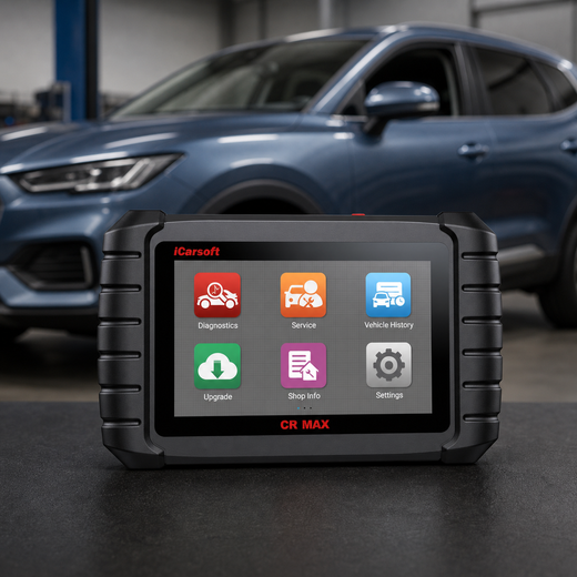
Save evidence before choosing a repair
iCarsoft CR MAX
Use a supported full-system scan to identify the modules reporting a communication fault and compare results before and after repair.
Check current CR MAX price and availabilityCheck CR MAX compatibility by VINUse an output test only if the precise cluster/ECU supports it and the service procedure calls for it. Gauge or lamp activation may help assess a symptom, but successful activation does not prove every network message or intermittent power path is reliable.
Know the measurement boundary. CR MAX does not directly measure harness continuity, terminal tension, supply voltage drop, network resistance or CAN waveforms. Those checks need appropriate external equipment and the correct diagram. Do not describe scanning as physical circuit testing.
Verify the U0155 Repair
After saving repair evidence, clear erasable codes according to the manufacturer’s procedure. Confirm communication with the cluster and the modules that originally reported U0155. Check gauges, warning indications and relevant functions under safe stationary conditions.
Repeat the specified wake-up, key-on and shutdown sequence and, when appropriate, a safe road test. Recheck for current and returning history faults. A cluster that wakes once after reconnection has not necessarily passed an intermittent-fault investigation.
Confirm restored communication, not just an empty code list. The cluster must remain reachable and operate correctly under the conditions that caused the fault. Use the manufacturer’s code-status definitions; a history network record is not automatically the same as an emissions permanent DTC.
Related Network and Module Communication Code Guides
U0155 Frequently Asked Questions
Does U0155 prove the instrument cluster has failed?
No. Missing power, poor ground, network faults, gateway behavior or application-specific software can interrupt cluster messages. Identify the reporting module and verify cluster access before applying the OEM pinpoint test.
Can a weak battery trigger U0155?
A supply interruption can cause modules to restart or drop off the network, leaving communication records. Test battery condition and loaded power and ground paths. A history code alone does not prove the battery needs replacement.
Can I drive if the dashboard is blank?
Do not rely on a vehicle with essential gauges or warning indications unavailable. Stop safely and arrange diagnosis or recovery as appropriate. A separate history code with a normally operating cluster requires a different assessment.
Why does one scanner connect while another cannot?
Tools differ in enhanced-system coverage, supported protocols and vehicle selection. Check exact cluster access and any gateway restrictions before treating failed tool access as evidence of a faulty module.
How much does a U0155 repair cost?
The fault may involve a connector, electrical supply, software or the cluster itself. A national cluster-replacement estimate is only relevant once that repair has been confirmed. Obtain a VIN-specific quote for the actual fault and required setup.
Will clearing U0155 or disconnecting the battery fix it?
Clearing removes erasable diagnostic records; it does not restore a defective circuit or correct incompatible software. Save the evidence, repair the confirmed cause and verify communication through the relevant operating sequence.
Technical and cost references
- GM 20-NA-021: Intermittent Service Steering Column Lock message displayed with U0155 Set — February 2020
- Mazda 15-001/19: Front camera sensor system malfunction warning and U0155:00 — January 30, 2019; specific CX-5 applications
- RepairPal: Instrument Cluster Replacement Cost Estimate — updated September 3, 2026
Product information: Official iCarsoft CR MAX page.
Editorial note: Use current manufacturer instructions for your VIN and qualified help for work beyond your training. A code identifies a test result, not a confirmed failed part.


