

Quick Answer
On the GM applications covered here, C0040 identifies the right front wheel speed sensor circuit. Read the complete symptom suffix and OEM description. The code does not prove the sensor itself has failed. Save the ABS scan report, identify the sensor technology, and compare electrical and wheel-speed evidence before replacing a sensor or hub.
What Does the C0040 Code Mean?
The C0040 code directs attention to the right front wheel-speed information on the GM systems described in this guide. The brake controller uses wheel-speed inputs for functions such as ABS, traction control, and stability control. A circuit or signal problem can cause the controller to limit assistance and display warning messages.
Read the complete fault, including any symptom byte or suffix. The base number alone does not distinguish an open, short, erratic signal, or another monitored failure. Confirm the actual description in the VIN-specific service information. Do not assume a code-number interpretation transfers unchanged between manufacturers or brake-controller generations.
The sensor, its connector, the moving harness, the encoder or tone ring, and the bearing assembly form one information path. A healthy sensor cannot report a clean signal if its target is damaged or the connector interrupts its supply. Conversely, a damaged wire can create a wheel-speed fault with a mechanically sound hub.
GM PIC5780, November 2012, covers C0035/C0040 symptom 0F on specified 2012–2013 Chevrolet Sonic vehicles. It illustrates wiring and bearing/hub checks; its scope does not establish universal repair specifications.
C0040 and related wheel-speed faults
| Code | General description | Key distinction |
|---|---|---|
| C0040 | Right front wheel-speed circuit on covered GM systems | Read the complete suffix before choosing tests. |
| C0035 | Left front wheel-speed circuit on the same systems | Do not interchange the corner being tested. |
| C0050 | Right rear wheel-speed circuit on covered systems | Use the correct rear sensor and harness layout. |
| U0121 | Lost communication with the ABS controller | Establish module power and network communication first. |
Two wires do not prove a passive sensor. Some active sensors also use two wires. Identify the electrical design from service information before choosing resistance, voltage, current, or waveform tests.
C0040 Symptoms and Likely Causes
The warning pattern depends on the vehicle and the fault status. A generic engine-only code reader may miss the relevant brake-controller details. Scan the supported ABS module and record the exact warnings together with current and history faults.
The vehicle may disable or limit assistance while the wheel-speed information is unreliable.
A signal dropout may contribute to unexpected ABS operation. Abnormal braking must be assessed before further driving.
Supported live data may show one corner behaving differently. Confirm comparable wheel motion before interpreting the trace.
Steering, suspension travel, vibration, or moisture may expose a wiring or connection problem that is absent while parked.
Practical cause-checking order
- Connector or moving harness: Inspect damaged insulation, corrosion, poor terminal retention, stretched wiring, and missing clips. Front-wheel harnesses must accommodate steering and suspension movement without rubbing or tension.
- Supply, return, or signal path: An active sensor needs the correct circuit conditions. An open, short, or high-resistance connection may interrupt the signal without an internal sensor failure. Follow the symptom-specific test branch.
- Encoder or tone-ring damage: Depending on design, the target may be a toothed ring or a magnetic encoder integrated into a bearing. Contamination, damage, incorrect installation, or a wrong replacement part can affect the information path.
- Bearing, hub, or mounting condition: Excessive movement, corrosion beneath a sensor, or incorrect seating can change the relationship between sensor and target. Use the correct inspection method and mounting specification rather than a guessed air gap.
- Sensor or brake-controller fault: Consider component replacement only after the supporting circuit and target are tested. Controller diagnosis comes after required powers, grounds, network checks, and the applicable external-circuit tests.
Do not apply generic resistance or AC-output limits to an active sensor. Do not use a test lamp or inject voltage into a sensitive sensor circuit unless the OEM test explicitly allows it.
How Serious Is C0040, and Can You Drive?
An amber ABS warning does not by itself establish the condition of the basic hydraulic brakes. It can indicate that an assistance function is unavailable. Read the owner’s manual and arrange prompt diagnosis; do not assume the vehicle will provide normal ABS or stability intervention during an emergency.
A vehicle with normal pedal feel and no additional warning still needs a cautious, application-specific assessment. Conditions such as rain, ice, towing, or heavy traffic increase the consequences of unavailable assistance. A fault code is not permission to perform a risky braking experiment to see whether ABS works.
Stop and arrange a tow Stop and arrange professional help for a red brake warning, low fluid, leakage, a soft or sinking pedal, pulling, grinding, or unexpected braking. Do not road-test a vehicle with an unresolved braking safety concern.
Use approved lifting points, wheel chocks, and rated stands before inspecting a raised wheel. Keep hands and leads away from rotating parts. Do not power driven wheels while the vehicle is on improvised supports. Use a qualified technician and the OEM procedure for any test requiring rotation, hydraulic work, or brake-system service.
How to Diagnose C0040 in the Right Order
-
Save the complete ABS code and warning history
Read all accessible modules and save the brake-controller report before clearing codes. Record C0040 with its exact suffix, module identification, status, and any freeze-frame or failure records available. Note the warning messages and whether the concern follows steering, bumps, low-speed stops, rain, or recent hub or brake work.
Preserve history faults and compare their timing with network or voltage problems. Distinguish the original codes from faults introduced by intentional disconnection during diagnosis.
-
Identify the sensor design and correct wheel circuit
Use the VIN, brake-system option, connector view, and wiring diagram to identify the right front circuit. Establish whether the sensor is passive or active and whether the encoder is separate or part of the bearing. Confirm the replacement hub or sensor specification if the fault began after previous work.
Do not infer architecture solely from the number of wires or the appearance of the connector. The chosen electrical test must suit the design. A passive pickup and an active current-modulated sensor can require very different instruments and interpretation, even when both connect through a small two-terminal plug.
-
Inspect the harness, mounting, hub, and target
With the vehicle safely supported as required, inspect the harness along its full accessible route. Check terminal condition, connector seals, routing clips, and areas that move with steering. Inspect the sensor mounting area and target according to the design. Look for damage or debris without assuming an apparently clean surface proves the circuit sound.
Check bearing movement and hub condition using the manufacturer’s method. Verify sensor seating and the correct side or orientation of a magnetic encoder when applicable. Use approved cleaning methods; do not scrape delicate encoder surfaces or use an arbitrary shim to create a guessed gap. Record any defect before disturbing it.
-
Compare wheel-speed data under controlled conditions
On a supported vehicle, graph the available wheel-speed PIDs during the safe test specified by service information. Compare corners under comparable conditions and note whether the right front signal drops, spikes, or starts reporting later. Steering and different tire paths can legitimately produce different wheel speeds; context matters.
A graph identifies when information becomes unreliable, but it does not locate the electrical defect by itself. Keep the diagnostic display out of the driver’s hands. Use a second qualified person or a recording function where appropriate, and stop testing if braking behavior is abnormal. Do not bypass safety systems to force a test.
-
Prove the electrical signal with the correct instrument
Follow the full-suffix pinpoint test. For an active design, verify the specified supply and signal behavior using suitable breakout equipment, a meter, scope, or current-measuring method as required. For a passive design, use only the specified resistance and generated-signal checks. Record test conditions and compare with the actual service limits.
Where directed, compare the signal near the sensor and at the controller to separate a target or sensor issue from a harness problem. Inspect terminal grip and movement-related intermittents. Do not assume a continuity beep proves the circuit will remain reliable during steering or vibration. Isolate power and electronics correctly before resistance testing.
-
Repair the confirmed defect and retest the same conditions
Repair wiring or terminals with approved sealing and routing methods, or replace a sensor or hub only when the evidence supports it. Follow the specified fastener torque, bearing installation, and any one-time-use hardware requirements. There is no universal sensor-bolt torque or hub procedure that safely fits all vehicles.
Reassemble the vehicle fully, confirm all connections are locked, and repeat the original safe test. Check the wheel-speed trace, relevant code status, warning behavior, and any required setup. Save the after-repair report. If the original fault was intermittent, document the conditions reproduced instead of treating one clean stationary scan as proof.
Specifications are vehicle-specific. Use the exact OEM sensor, air-gap, supply, waveform, bearing-play, and fastener specifications. No universal resistance, AC-voltage output, missing-tooth count, or mounting torque is supplied here.
C0040 Repairs and Cost Factors
Repair the failed section of the signal path. A harness fault needs a durable electrical repair and correct movement clearance. A damaged encoder or bearing may require a hub assembly on one design and a different component on another. Order parts using the VIN and brake-system configuration.
Do not replace the brake controller because the sensor reading is missing. First prove its required power, ground, network, and external sensor circuits. If hydraulic components are disturbed, follow the complete manufacturer bleeding and service procedure; code clearing alone cannot verify hydraulic braking performance.
| Possible path | US quote requirements |
|---|---|
| Wheel-speed diagnosis | Request suffix-specific electrical tests and a controlled data comparison. |
| Harness or terminal repair | Include approved connector parts, sealing, and restored routing. |
| Sensor or hub replacement | Identify the proven defect, exact part, hardware, and installation labor. |
| Controller diagnosis | Require external-circuit and module supply evidence before approval. |
Obtain a VIN-specific written quote after the fault is isolated. A sensor replacement, integrated hub repair, and intermittent harness repair have different labor and parts requirements. Ask the shop to separate diagnosis, repair, taxes, and verification so competing estimates cover the same work.
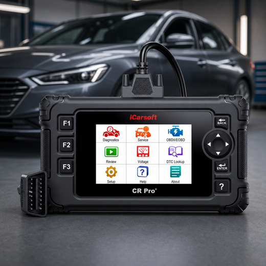
Using iCarsoft CR Pro+ for C0040
The official CR Pro+ page lists all-system diagnostics and bidirectional control. Confirm the exact ABS module, wheel-speed PIDs, suffix reporting, and any required function before purchase; successful engine communication does not prove ABS coverage.
Use a focused set of available wheel-speed data and retain the original scan report. Pair any observed dropout with an electrical or mechanical test. A scanner can display what the module reports; it cannot by itself decide whether the sensor, encoder, bearing, or connector is defective.
Save evidence before choosing a repair
iCarsoft CR Pro+
On a supported vehicle, the CR Pro+ can help read ABS faults and compare wheel-speed data while you test the physical signal path.
Check current CR Pro+ price and availabilityCheck CR Pro+ compatibility by VINUse an active test only when the exact VIN, controller, and function are supported and the OEM procedure calls for it. Do not run an ABS pump or valve test merely to address a wheel-speed code. Never describe the scanner as physically testing hub play, terminal tension, or sensor resistance.
Know the measurement boundary. Physical voltage, current, waveform, resistance, bearing movement, and encoder condition require the correct external instruments and inspection. The scan tool is one source of evidence alongside those tests.
Verify the C0040 Repair
Confirm the repaired wheel-speed signal remains plausible during the original safe operating conditions. Check full DTC status and warning behavior in the ABS controller, then review related modules for consequential faults. Use the manufacturer’s clearing and test sequence after saving the evidence.
For C0040, verify the chassis-system repair directly. Emissions readiness and permanent powertrain-DTC rules are not a substitute for an ABS test. A light that goes out immediately after clearing does not establish that the sensor signal or braking system has passed its required checks.
Save the final ABS report and the test conditions. Confirm the relevant chassis diagnostic passes and the original warning or signal dropout does not return; do not apply a generic permanent-emissions-code drive cycle to C0040.
Related ABS and wheel-speed Code Guides
C0040 Frequently Asked Questions
Does C0040 prove the right front sensor is bad?
No. On the covered GM systems, the code identifies a circuit or signal path. Wiring, connectors, the encoder, bearing condition, and the sensor itself need appropriate tests.
What does the C0040 suffix mean?
The suffix narrows the monitored failure. Save the exact code and use its OEM description and pinpoint test; the base C0040 number alone is insufficient.
Can I test every wheel-speed sensor with an ohmmeter?
No. Identify active versus passive design first. An active sensor may need supply and current or waveform testing; a generic resistance test can be misleading or inappropriate.
Can a wheel bearing cause C0040?
It can contribute on relevant designs through movement or an integrated encoder fault. Prove the mechanical or target problem rather than replacing a hub solely because C0040 is stored.
Can I drive with an ABS warning?
The answer depends on brake condition, warnings, and the owner’s manual. Assistance may be unavailable. Stop for abnormal braking, red brake warnings, leakage, or a soft pedal and arrange professional assessment.
How is a C0040 repair verified?
Repeat the safe conditions that caused the fault, compare wheel-speed information, and confirm the relevant ABS diagnostic and warnings. A cleared code while stationary is not sufficient.
Technical references
- GM PIC5780 — November 2012; specified Chevrolet Sonic C0035/C0040 symptom 0F
- GM PIT5593B — published May 28, 2020; full-module DTC context and wheel-speed examples
Product information: Official iCarsoft CR Pro+ page.
Editorial note: Use current manufacturer instructions for your VIN and qualified help for work beyond your training. A code identifies a test result, not a confirmed failed part.


